Mechanics & Electronics
This section lists all mechanical and electronic parts on the prototype.
All images are from the linked product page unless otherwise noted. All specifications on communication protocols, voltages, etc. are taken from the linked product datasheet unless otherwise noted.
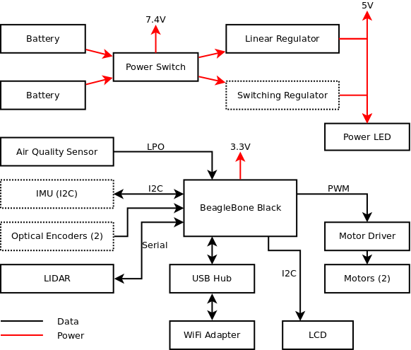
The image below shows a block diagram of the hardware on the robot. All hardware on the robot connects to the BeagleBone Black through a custom circuit board. A block diagram of this board is shown below. In this diagram the red lines indicate power flow and black lines indicate data flow. Dotted lines indicate a component is not in use in the current works-like prototype. The first version of this board was on a prototyping board, which contains all hardware shown in the diagram with the exception of the switching regulator.
A BeagleBone Black (BBB) running Ubuntu is the main computer, and connects directly to all the hardware. All the electronics are powered by a 2-cell 7.4V Lithium Ion battery, either directly, through a 5V regulator, or through a 3.3V regulator internal to the BBB. There are two batteries for increased battery life. The current prototype uses a linear regulator; a switching regulator is also present but is not fully operational. A power LED indicates whether the robot is powered on. The connection protocol used for each device is also shown. The connection to the user’s computer is over standard WiFi, and thus requires a WiFi network to be set up. This will be the case in many, but not all, environments. The WiFi adapter is connected to the BeagleBone Black through a USB hub to maximize the available power to the adapter. The motor driver controls the speed and direction of the motors. The LCD displays basic status information such as the IP address assigned to the robot. All hardware except the switching regulator is fully assembled.
There are two optical encoders on each wheel for a total of four sensors, which measure the speed and direction of rotation of the wheels. The inertial measurement unit (IMU) measures acceleration, angular velocity, and magnetic fields, which can be used to determine the robot’s relative motion. These two components are functional but are not used in the current prototype. A webcam was present in the initial prototype but was removed as few industry representatives found appeal in a livestream of the robot’s path. The LIDAR measures the distance to obstacles 360° around the robot.
The air quality sensor measures airborne particle count every 30 seconds.
Chassis
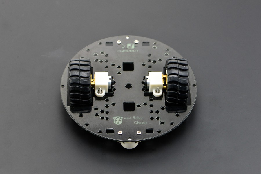
The robot chassis is a 2-wheel-drive miniQ platform with 5” diameter manufactured by DFRobot. This chassis was chosen as it is inexpensive, large enough to fit all the electronics, and matching optical encoders are available. A third caster-type wheel provides stability.
BeagleBone Black
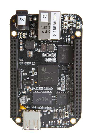
The main processor board on the robot is a BeagleBone Black (BBB), which is a development board for the TI AM3359 ARM Cortex A8 microprocessor. This board provides the following functionality, which was deemed necessary or useful for the robot:
1GHz ARM processor - this processor is fast enough to run a full operating system (Debian Linux) which allows us to use standard desktop development tools and libraries. The relatively high clock speed allows us to run computations such as localization from LIDAR readings, which is not possible on low-power microprocessors such as Arduino.
PRU and ICSS - this processor contains two PRUs which can be used for real-time data processing or communication with external sensors. The ICSS is a low-latency method of communication between the main processor and the PRUs. These PRUs are necessary as Linux is not a real-time OS and thus is not capable of responding to events in real-time–there is always some delay as it finishes what it is currently doing and switches tasks.
On-board Flash storage - The existence of on-board storage simplifies our development process as we do not have to implement storage on our circuit board
GPIO - The BBB has a significant number of GPIOs, including hardware peripherals such as UARTs and I2C. These are necessary to communicate with the various other electronics on the robot.
Low cost - The BBB is between $45 and $55 depending on the distributor. This is very inexpensive for the functionality and competitive with similar alternatives.
Open source - All design materials for the BBB board are open source and publicly available, which makes building a final product much easier. All parts used on the board are available from distributors such as Digi-Key in low quantities, making prototyping a final product cheaper, and all parts have publicly available documentation, meaning no non-disclosure agreements are necessary.
The most compelling alternative to the BBB is a Raspberry Pi. At the time we began this project, the Raspberry Pi did not have a sufficient number of GPIOs and was not capable of running recent Linux software, and thus was not a feasible choice. The Raspberry Pi 2 was released during our development which fixes these two concerns, and adds a quad-core processor, but it still does not have a real-time unit.
WiFi Adapter
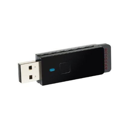
A Netgear N150 WNA1100 USB WiFi adapter is used for wireless communication with a laptop running the web interface. This adapter was chosen as online reviews stated it worked with the Raspberry Pi, which is similar to the BBB.
An inexpensive USB switch purchased on eBay is used to power the adapter. The 5V supply line to the switch, which normally would be connected to the USB port on the BBB, was cut and connected directly to the output of the linear regulator instead. This was done as the output current of the BBB USB port is limited and was not sufficient to power the WiFi adapter.
Wheels, Motors, and Motor Driver
The wheels and motors used on the robot are those included with the miniQ chassis. The motors are compatible with the Polulu micro gearmotors, which are very popular in small-size robots, are easily obtainable, and are low cost. The choice of wheel is not critical for the robot, but we continued using the included ones as we did not encounter problems with them, and there is an integrated encoder wheel on each one.
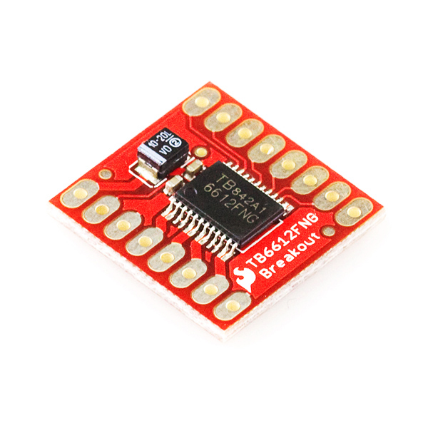
The motor driver is a TB6612FNG. This was chosen as it works with the BBB with no additional parts, can control both motors at once, and is very low cost. The speed of each motor is controlled by a PWM signal, and the direction by two digital signals.
Optical Encoders
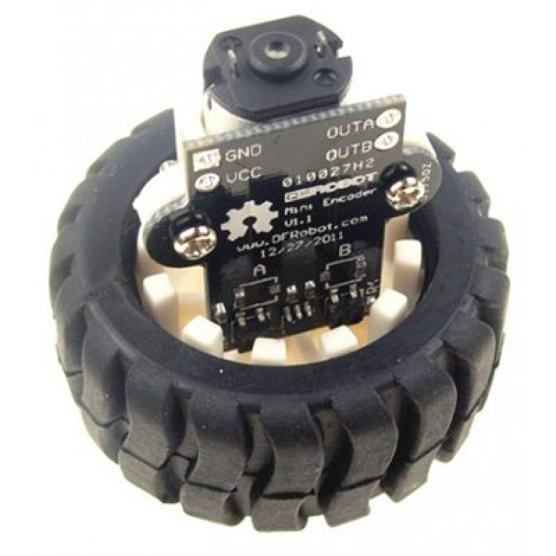
Each wheel has two optical encoders which are designed to work properly with the chassis and motors. These measure the direction (forwards/backwards) and speed of rotation of each wheel. The optical encoders can theoretically be used to calculate the position of the robot for short periods of time.
The encoders are not used on the current prototype (although they are still present) as they did not give consistent data. The output pulse train would frequently skip values, and the two encoders were not synchronized properly to give direction.
IMU
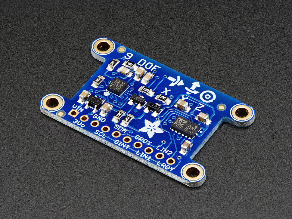
The Inertial Measurement Unit measures linear acceleration, angular velocity, and magnetic fields in all three dimensions. Communication with the IMU is done over I2C; this is the only part that requires a 3.3V power supply and thus cannot be combined on the same I2C bus with other components such as the LCD. An IMU can theoretically be used to accurately calculate orientation, however we experienced a large error from the sensor that made the calculated orientation useless. An IMU can also theoretically be used to calculate position by integrating the acceleration, however cumulative error made that calculation less accurate than other methods. The IMU is no longer present on the current prototype.
LIDAR
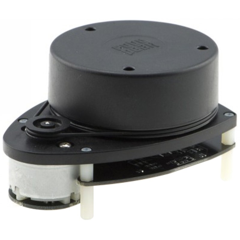
The LIDAR is the RPLIDAR manufactured by Robopeak and is used to detect walls and corners in the environment for localization.
It includes both a laser rangefinder and motor, and measures the distance to obstacles 360° around the robot approximately twice per second. The maximum range is 6 meters and the minimum is approximately 10 cm (determined experimentally), outside these values the distance is reported to be 0. This laser is rated at Class 1, indicating it is safe for use near humans and no precautions need be taken.
The LIDAR communicates over serial at a baud rate of 115,200 and a high voltage of 3.3V. This is connected to the UART5 on the BBB. A third pin is used to control the speed of the motor using PWM.
- Product page
- Robopeak, “Low Cost 360 degree 2D Laser Scanner (LIDAR) System: Introduction and Datasheet,” RPLIDAR datasheet, May 2014, Revision 7
Air Quality Sensor
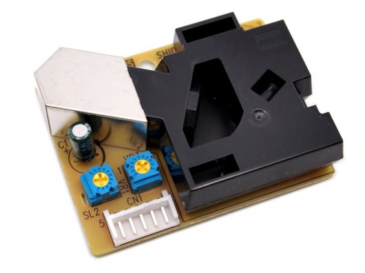
The air quality sensor is the Shinyei PPD42NS, a simple, commercially available sensor that measures airborne particle count. It lacks both the high resolution and sophisticated data collection/delivery desired by industry experts consulted, but it is functional and integrates well with the works-like prototype.
The minimum particle size measured is 1 micrometer diameter, particles below this size are invisible to the sensor. In addition, the first two measurements are invalid as the sensor is warming up. The sensor output is normally high (> 4 V), and goes low when a particle blocks the sensor; the duration of the low pulse is determined by the size and count of the particles. Readings are obtained by calculating the percentage of time the output is low over a 30 second period.
The signal from this sensor is read using one of the PRUs on the BBB, not directly in Javascript. The value is transferred to shared memory every 30 seconds. This is done as the duration of each low pulse must be measured accurately to determine the low pulse occupancy time, and due to its design, Javascript is not capable of accurate timing short durations. The PRU code is written in Assembly.
LCD
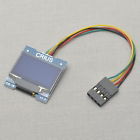
The LCD is the CRIUS CO-16, a 128x64 pixel OLED display. It is very similar to the Monochrome OLED Breakouts maufactured by Adafruit and SparkFun, and uses the same SSD1306 controller. Communication with the LCD is done using I2C. It is used to display the WiFi network status, particularly which network the robot is connected to and which IP address has been assigned to it. This display was chosen as it is very compact, so it does not take much space on the robot, it can display enough characters for our needs, and the high contrast of an OLED makes it easy to read in bright lights.
As OLED displays can show arbitrary pixels and not just pre-defined characters, it could also be used to display menus, images, or visualizations of data in a future prototype.
- Image source: eBay product listing, link no longer available
- SSD1306 Datasheet
Battery and Power Supply
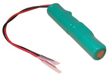
The robot has two dual-cell 7.4V, 650mAh Lithium Ion batteries manufactured by BatterySpace. The dual battery design was chosen so that one battery could be charging while the other is used to power the robot during testing without having to physically swap batteries. A final product would use a single, larger battery.
The charger is manufactured by BatterySpace and designed to work with this battery.
The electronics are powered by a 5V LM7805 linear regulator. This was chosen as it is inexpensive, widely available, and very easy to use. Due to the high current draw of the BeagleBone Black and LIDAR, a heat sink was mounted to the regulator.
The custom PCB also contains a second switching regulator, however the layout is incorrect and thus it is not functional. This was included to increase efficiency of the power supply circuit to improve battery life.
PCB
The current prototype uses a prototyping breadboard cape to connect the electronics to the BeagleBone Black. A custom PCB was designed using CadSoft Eagle to replace this, to improve looks, reduce noise, and to add a switching regulator.
The linear regulator circuit is identical to that on the prototyping breadboard, except for the addition of the 2-pin jumper to control whether the regulator is active. It uses an LM7805, which is a very common 5V regulator.
The switching regulator is a TI TL2575 buck regulator, chosen as it is relatively inexpensive, simple to use, and provides enough current. It has a fixed 5V output (simpler than adjustable) and 1A maximum output current. The external capacitors, diode, and inductor were chosen according to the datasheet’s guidelines.
Power MOSFETs were added on the ground supplies to three components which were measured to use a significant current. These are BUK9277 N-channel surface-mount devices, chosen as they are capable of providing a large enough current and they were already on hand.
The PCB is not in use due to the following issues:
- The TI TL2575 buck regulator footprint/layout is the incorrect size–it is too small for the part. We used the layout in Eagle that matched the part and did not measure it to ensure it was the correct size. This does not make the PCB useless as the linear regulator may be used instead.
- One connection to the 680uF capacitor is missing, this was fixed by adding a wire to the board and thus did not negatively impact the board in any way.
-
The power MOSFETs work properly, however their design causes the BBB to be fried upon power-up. Their default state is off, resulting in 5V being applied to the three components with no ground connection. Due to the internal design of the components, this caused the LIDAR and optical encoders to output 5V on their signal lines. According to its manual, the BBB cannot have a high voltage applied to its pins on power-up; when we connected it, the BBB was in fact fried. This may be fixed by either changing the default state to on (replacing the pull-down resistors with pull-up resistors) or using P-channel MOSFETS to switch the 5V supply instead.
- PCB Schematic
- PCB Layout
- PCB Layout Mask
- TI TL2575 Buck Regulator product page
Power Consumption
Current draw of all parts was measured with a digital multimeter in various modes of operation and is listed in the table below. All components (with the exception of the motors) were powered through a 5V linear regulator. The multimeter was placed in series between the regulator and multimeter to include power loss within the regulator. As most components cannot operate normally without being connected to the BBB, it was included in the measurements, and later subtracted.
| Device | Current (mA), measured as drawn from the battery | Current if regulator efficiency was 77% instead of 63% | Current goes through regulator? |
|---|---|---|---|
| BBB (idling) | 180 | 147 | Y |
| BBB (busy) | 320 | 262 | Y |
| WiFi (disabled) | 40 | 33 | Y |
| WiFi (connected) | 100 | 82 | Y |
| Optical Encoders | 100 | 82 | Y |
| AQ sensor | 80 | 65 | Y |
| LIDAR (not spinning) | 50 | 41 | Y |
| LIDAR (spinning) | 160 | 131 | Y |
| Servo | 10 | 8 | Y |
| LCD | 0 | 0 | Y |
| IMU | 0 | 0 | Y |
| Motor Driver (on standby) | 0 | 0 | Y |
| Motors | 100 | 100 | N |
Note: Italicized rows indicate a busy state for that component. Non-italicized rows indicate an idle state, or that the component was measured in only one state.
The efficiency of the linear regulator is determined by the following equation. Output voltage is fixed at 5V, input voltage is the battery operating voltage, which varies and was chosen as 8 V for the worst case.
Efficiency = Output Voltage / Input Voltage = 5 / 8 = 63 %
We also calculated what the power consumption of each component would be with a switching regulator with efficiency of 77%, which is a common efficiency among several commercially available parts researched.
Based on these measurements we calculated the total current draw and expected battery life with a 650mAh battery with both a linear and switching regulator, shown in the table below. We also calculated the total current draw and expected battery life with MOSFET switches added on the power supply to the optical encoders, air quality sensor, and LIDAR.
| Scenario | Current (mA) | Battery Life (hrs) |
|---|---|---|
| Idling with no hardware switches (Linear) | 460 | 1.4 |
| Idling with no hardware switches (Switching) | 376 | 1.7 |
| Idling with hardware switches (Linear) | 220 | 3.0 |
| Idling with hardware switches (Switching) | 180 | 3.6 |
| All components busy (Linear) | 870 | 0.7 |
| All components busy (Switching) | 730 | 0.9 |
The robot has two 650mAh batteries and a linear regulator, thus expected battery life in the worst case (all components busy) is 1.4 hours, and expected battery life in the best case (idling with hardware switches) is 6.0 hours.